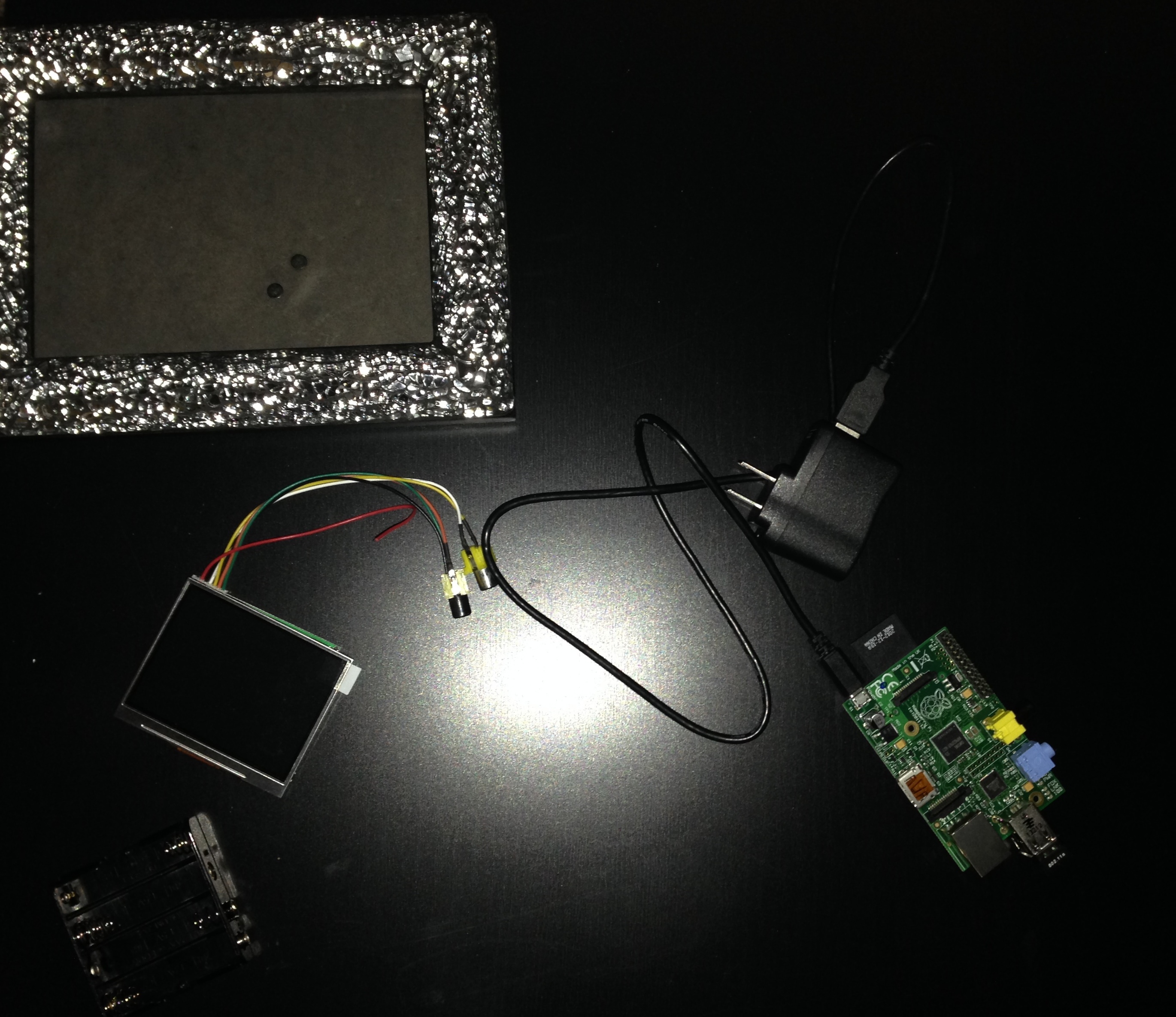
Adafruit sells some really cute LCD screens for the Pi. I recently purchased such screen and decided to solder the screen directly to my Pi after seeing this guy’s cool pi project.
So to catch up on what I’ve done so far on my Pi, check out this post. The following steps discuss my experience soldering the pieces together.
Equipment
- My Pi
- Soldering Iron (Aoyue 937+ is about $63 on Amazon)
- Solder ($8.16 Amazon Prime)
- Battery Holder ($3.86)
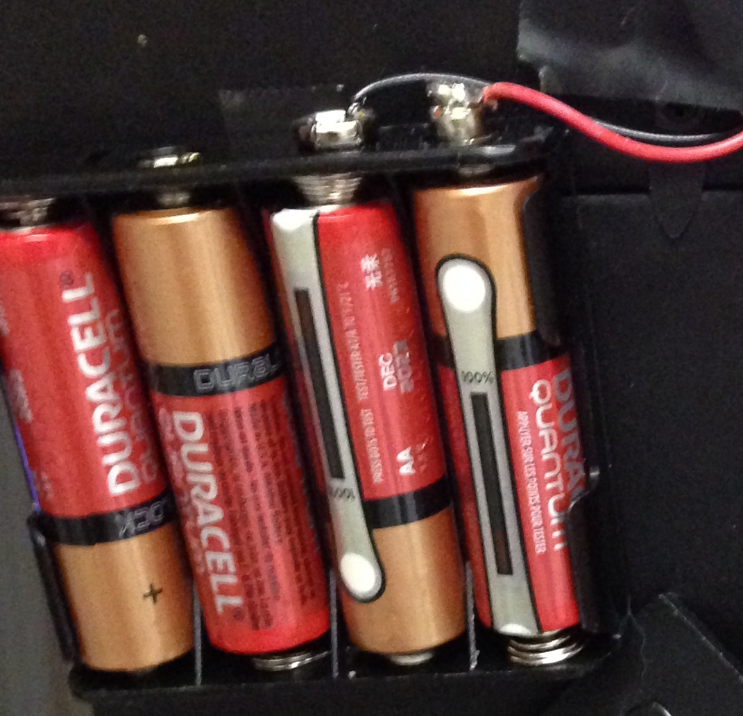
- 4 AA Batteries
- Electric Tape
- Double Sided Tape
- A frame to hold it all
Putting the Parts Together
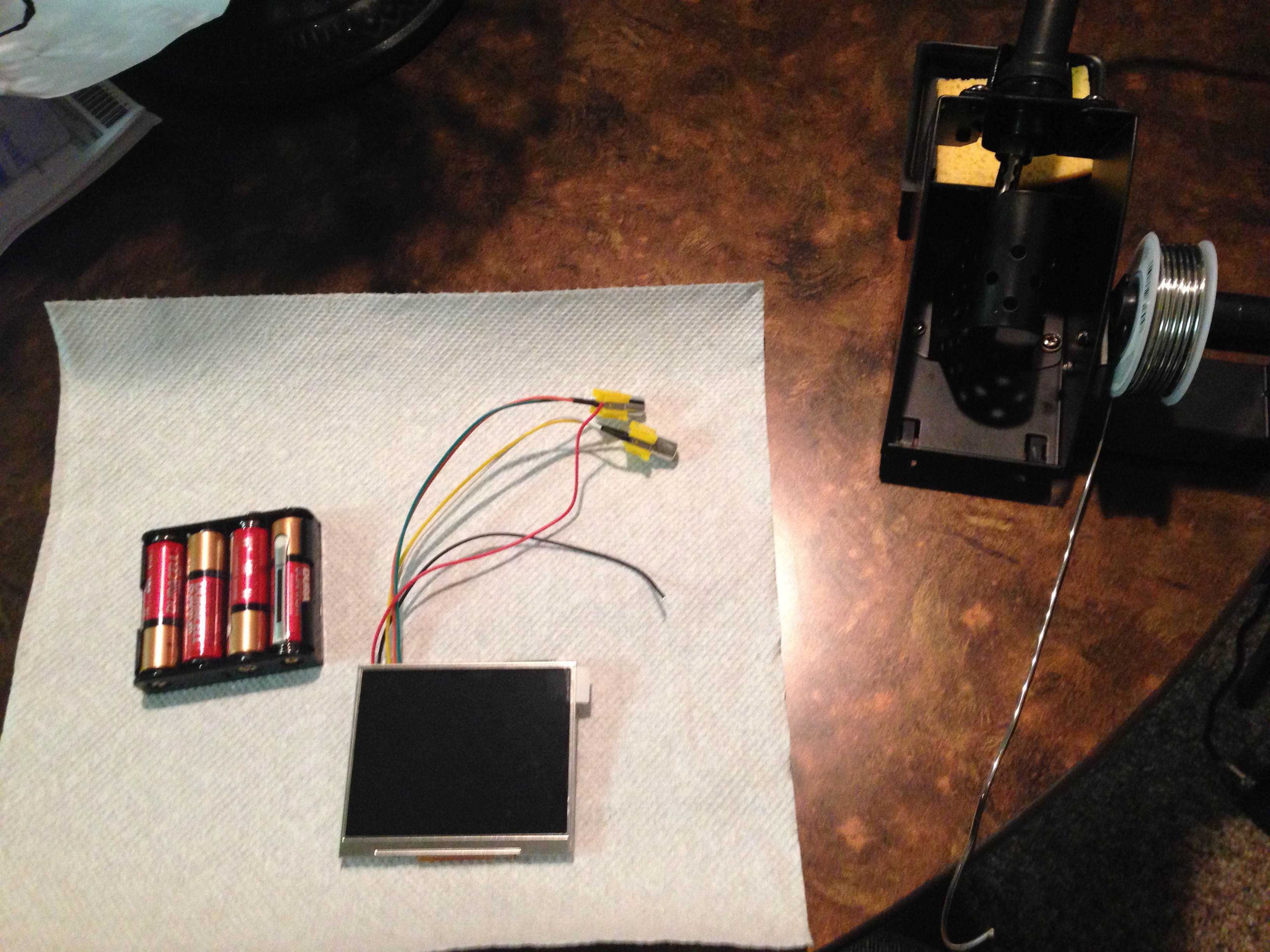
I first soldered the LCD power lines to the batter pack. The LCD runs on 6-12V. I found this cheap battery holder on Amazon that could hold four AA batteries or 6V total. The power lines are the two that did not come attached to one of the two RCA connectors. Solder the red to the positive (+) battery pack output and the black to the negative (-) output. Think as red surging hot with power and the black as dead or negative of surging power.
Not sure this is the best soldering technique but I normally tint the soldering iron tip with a bit of solder first then I set that tip against the connection point. Last, I’ll stick the wire into the hot solder on the iron touching the connection point before carefully removing the iron from the solder.
I had batteries in the holder during this process so I could see the LCD powered on and ensure the wires were soldered correctly in place. Just be careful, don’t shock yourself.
Next, I cut off one of the RCA connectors. Basically one connector is a backup for the other, if there isn’t a signal coming in on one, the other is checked or used. It does not matter which one you choose to hook up to the screen. Make sure not to cut off too much wire during this process.
Following, I striped some of the insulator back off the wire then soldered it to the board. The picture below shows where I soldered everything on the under side of the Pi. Your colored cables might not be the same as mine. Test everything before you actually solder it onto the board. It’s easy just power on the Pi and test the wires to see what actually outputs video to the Pi.

Tah dah! Now everything is hooked up! I then taped it all to a frame to make it pretty.


From here, you may be interested in having the Pi auto login (not advisable but I did it) and boot startx (the desktop GUI). This was the most helpful tutorial for accomplishing the auto boot stuff.
I’m pretty proud.