Overclocking the Pi

Today, I wish to speed up my Raspberry Pi, it’s just too slow in opening up applications and jazz. After a google search on common ways to speed up your Pi I accumulated the following list of improvement methods:

  • Ensure you have the right type of SD card for the load, SDHD is good
  • Make sure you are getting the most out of you SD card by maximizing the partition. (I explained how to do this in this post)
  • Kill X applications, or the GUIs such as the desktop (In my case, I want the GUI so that’s not going to happen)
  • Use insserv –r to remove unwanted startup or init scripts
  • Overclock the sucker!

Overclocking

According to Wikipedia, “…overclocking is the process of making a computer or component operate faster than the clock frequency specified by the manufacturer by modifying system parameters.”

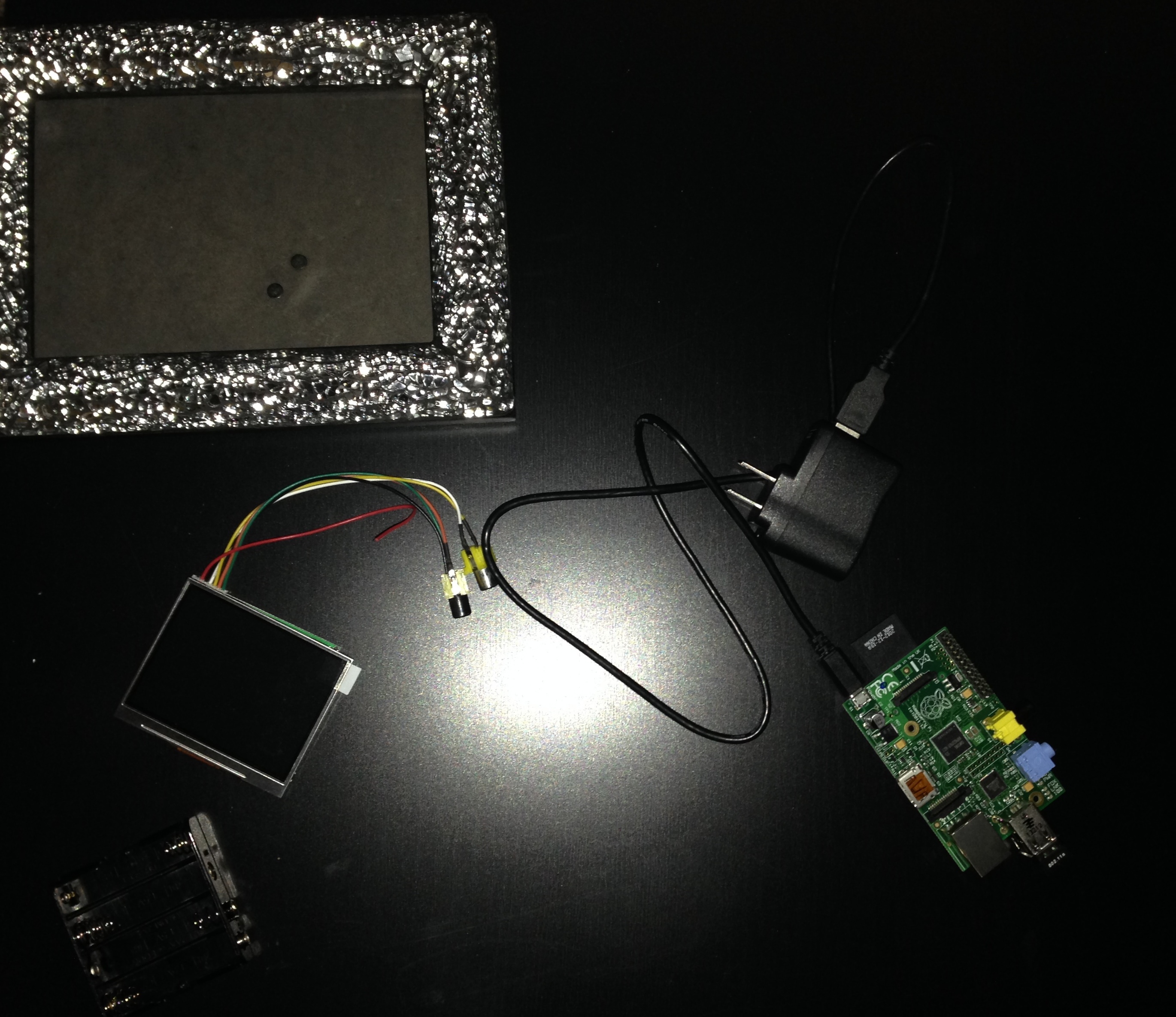
WARNING: Before overclocking your Pi be warned that power consumption may increase. You should be using a quality power supply, such as a wall adapter. Also, your Pi may emit quite a bit of heat depending on how high you clock it. It would be wise to consider a fan or something to regulate the temperature of the device.

I followed the tutorial here quite a bit during my experience of dealing with Pi overclocking.

Basically, I used raspy-config, I explained how I installed the configuration tool on Kali here.

Command:

raspi-config

This will open up the Raspbian configuration menu.

Screen Shot 2014-02-11 at 9.08.07 PM

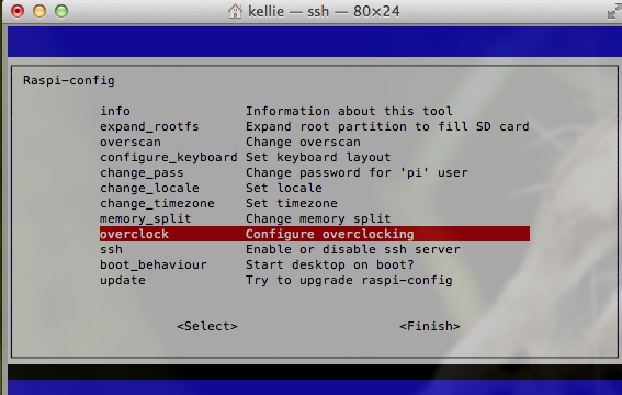
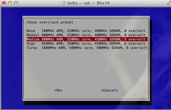
From the menu, select overclocking and choose your desired setting. Take the warning seriously, overclocking your system can shorten its life or even prevent the thing from starting up. Take things slow!

Screen Shot 2014-02-11 at 9.07.54 PM

Voila, reboot and there you have it.


Intel RAID 5 on Windows 8.1

I upgraded by Windows 8 to Windows 8.1 a couple of months ago and since the change I was getting blue screens (of death…) consistently.

This issue was do to a piece of memory that was incorrectly over written, my RAID drivers were also failing. There really wasn’t anything important on my Windows partition so I decided to delete the partition and reinstall Windows 8.1 as a fix. There are helpful debugger tools to deal with this along with memory tests but it was just as easy for me to delete and start over.

The following instructions apply to an Intel Motherboard.

Enabling RAID (I already had my RAID setup, so I didn’t need to perform these steps since it is configured on the hardware level.)

  1. Turn on the computer and during the first screen that  flashes the manufacturer name (the screen before the Windows logo) enter the BIOS menu. The screen flashes quickly and for those who don’t know how to enter this screen, it’s normally a F key. The manufacturer screen normally has on it a list of  key options, just look for the one that will get you to the BIOS configuration (Don’t worry if you miss it, just keep shutting down the machine and turning it back on until you get it). For me, the Intel key was “F2”.
  2. Under the configuration tab in the BIOS, set the “Chipset SATA Mode” to RAID. Directions on how to change values are displayed on the right hand side of the screen.
  3. Save changes and exit the BIOS screen (ESC key).
2014-02-01 09.43.41
BIOS Configuration Tab

Configuring RAID Volumes (Once again I already had this setup.)

  1. Reboot the computer. There should now be an additional screen that appears between manufacturer screens when you start the machine up. This lists all your RAID volumes.
  2. Quickly, press CTRL-I to get to the RAID configuration utility while the screen is up. This was actually tricky for me, I had to make multiple attempts. For some reason, I could not get this to work on my bluetooth keyboard but it worked with another keyboard… some bug. Even with a different keyboard, I basically held down CTRL and went crazy pressing “i” over and over and over again.
  3. In this window you can create RAIDS! Choose option 1 to create your volumes or look at the other available options for different functions.
  4. My settings consist of two bootable RAID 5 volumes across my three ~4TB (3.6TB actual) hard drives. One with 125GB and the other with 7.1TB. The screenshot below shows my setup for your reference. Depending on your setup (RAID 5 requires at least 3 hard drives), you may want to do some research into RAID and your options. I chose 5 because it is supported by my motherboard and provides mirroring/striping. So it optimizes parallel communications and provides redundancy. In the case that one of my hard drives fails, I won’t loose anything. If two hard drives fail… I’m screwed. Basically, you have some protection from failure but still replace bad hard drives ASAP.

2014-02-01 10.22.15

Install Windows

Intel Raid Driver I Used

  1. Download the Intel RAID drivers from their website and put them on a USB device. The screenshot above shows the driver I downloaded. Keep the USB plugged in during the following steps.
  2. I had a DVD with a Windows 8.1 ISO burned to it. This was placed into the computer before I shut it down. I then turned the computer on and again during the manufacturer/first screen, I hit the “F10” key to select from where to boot. Most of the time, by default you boot from the Windows partition on your hard drive. However, this time, I wanted to boot from my install DVD containing Windows 8.1.
  3. It took awhile to load the Windows menu, but once it did, I chose to “Install.”
  4. The next few screens deal with entering your license key and junk.
  5. Once I was prompted for Default or Advanced setup. I chose Advanced. This was because I needed to mess with the partitions.
  6. The next screen will show the existing partitions but we have RAID going on and to make the install aware of this, we need to provide the drivers. In the current window, look for and select “Load driver.”
  7. I pointed the device to my USB to search for drivers. Once it found my Intel RAID driver, I selected it and clicked “Next.”
  8. After a few minutes, you will be returned to the partition window and you should see you RAIDs correctly.
  9. Format a new partition for your Windows (I deleted the previous). In my setup, I have 8 TB of hard drive space. I dedicated 124 GB to my Windows partition and the remainder to a partition I call “cabinet.” This is where I store my documents, media, etc. Windows does have a problem with creating a partition greater than 2TB. These drives must use GPT. This page discusses more on GPT. If this is what you plan to do, don’t partition the larger now, wait to use the Windows disk utility described in the link.
  10. Continue and let Windows install. Was completed, install drivers as needed. Intel has a tool that helps with this process.
2014-02-01 01.13.18
Driver Selection
2014-02-01 01.13.21
Partition Window

There you have it!

PIR Sensor on the Pi

Today I soldered a PIR sensor to my Pi! Basically, I want it to detect movement and turn on a LCD screen, then turn the screen off again after a minute of no movement. So when I walk into a room, the screen turns on and when I leave, the screen turns off.

Equipment

Solder

First thing, I looked up the pinout for the Raspberry Pi. The below diagram comes from elinux.org.

We care about one of the 5V, ground and GPIO25 pins.

  • Solder the sensor red cable to either 5V.
  • Solder the black cable to ground.
  • End by soldering the yellow line to GPIO25.

Your results should be similar to my picture below.

back

Next, I used this guy’s pir.py script. The script requires the Python library RPi.GPIO. I installed this by downloading the library from here, the direct link is here. To untag or unzip the file I used the following command:

tar -xvf RPi.GPIO-0.5.4.tar.gz

Before installing it, make sure you have python-dev installed.

apt-get install python-dev

With that necessary package, install RPi.GPIO.

cd RPi.GPIO-0.5.4
python setup.py install

Now you can run the pir.py script. I made some slight changes to his code. I didn’t feel the need to call separate scripts to run a single command so I made the following edits.

import subprocess

to

import os

and

def turn_on(): 
    subprocess.call("sh /home/pi/photoframe/monitor_on.sh", shell=True)
def turn_off(): 
    subprocess.call("sh /home/pi/photoframe/monitor_off.sh", shell=True)

this

def turn_on(): 
    os.system("chvt 2")
def turn_off(): 
    os.system("chvt 2")

Run the script and test it out! The sensor will turn off after a minute of no movement and on again once it detects something. I ended by setting my script to run on startup.

2014-01-30 20.33.51

I need to put a picture in the frame to act as background to the pi…

Soldering an LCD to the Raspberry Pi

Adafruit sells some really cute LCD screens for the Pi. I recently purchased such screen and decided to solder the screen directly to my Pi after seeing this guy’s cool pi project.

So to catch up on what I’ve done so far on my Pi, check out this post. The following steps discuss my experience soldering the pieces together.

Equipment

  • My Pi
  • Soldering Iron (Aoyue 937+ is about $63 on Amazon)
  • Solder ($8.16 Amazon Prime)
  • Battery Holder ($3.86)
  • 4 AA Batteries
  • Electric Tape
  • Double Sided Tape
  • A frame to hold it all

2014-01-23 19.42.58

Putting the Parts Together

2014-01-23 19.56.18

I first soldered the LCD power lines to the batter pack. The LCD runs on 6-12V. I found this cheap battery holder on Amazon that could hold four AA batteries or 6V total. The power lines are the two that did not come attached to one of the two RCA connectors. Solder the red to the positive (+) battery pack output and the black to the negative (-) output. Think as red surging hot with power and the black as dead or negative of surging power.

Not sure this is the best soldering technique but I normally tint the soldering iron tip with a bit of solder first then I set that tip against the connection point. Last, I’ll stick the wire into the hot solder on the iron touching the connection point before carefully removing the iron from the solder.

2014-01-23 20.31.13

I had batteries in the holder during this process so I could see the LCD powered on and ensure the wires were soldered correctly in place. Just be careful, don’t shock yourself.

Next, I cut off one of the RCA connectors. Basically one connector is a backup for the other, if there isn’t a signal coming in on one, the other is checked or used. It does not matter which one you choose to hook up to the screen. Make sure not to cut off too much wire during this process.

Following, I striped some of the insulator back off the wire then soldered it to the board. The picture below shows where I soldered everything on the under side of the Pi. Your colored cables might not be the same as mine. Test everything before you actually solder it onto the board. It’s easy just power on the Pi and test the wires to see what actually outputs video to the Pi.

2014-01-23 20.21.54

Tah dah! Now everything is hooked up! I then taped it all to a frame to make it pretty.

2014-01-23 22.02.11
Back
2014-01-23 22.01.52
Front

From here, you may be interested in having the Pi auto login (not advisable but I did it) and boot startx (the desktop GUI). This was the most helpful tutorial for accomplishing the auto boot stuff.

I’m pretty proud.